Groundwater is an important resource in Oregon. As more people depend on groundwater, some water tables around the state are dropping, threatening their water supplies. State law requires that groundwater be managed as a renewable resource and that water tables do not drop permanently.
To assess the size of the groundwater resource and monitor the effects of development and drought, state law requires an aquifer test on every well with a water right. Part of that test is to measure the depth of water in the well. We’ll discuss three methods of measuring water levels in this publication.
First, let’s define our terms.
Glossary
Aquifer: A water-bearing geologic formation.
Column: Pipe leading from the surface down to the pump.
Drawdown: The vertical distance the water level is lowered when the well is pumped.
Groundwater: Water that naturally occurs in porous rock materials underground.
Static water level: The depth below ground level where water stands in a well when it’s not being pumped (also water table).
Electric sounder or electric depth gauge
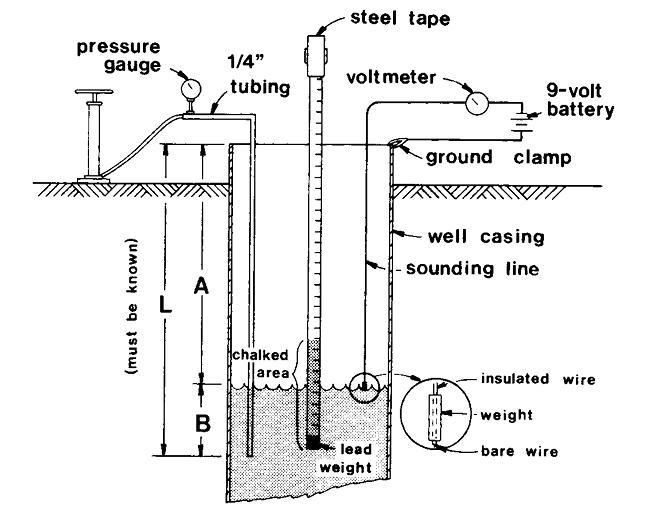
This is perhaps the handiest method for measuring well water levels. It consists of a weight suspended on #16 or #18 stranded insulated wire with depth markings and an ammeter to indicate a closed circuit.
Current flows through the circuit when the end of the wire touches the water surface. Current is supplied by a small 9- or 12-volt battery. To make a reading, lower the electric wire or sounding line until the needle deflects.
Read the distance from the water to the top of casing on the line (see Figure 1). Mark the reference point on the casing where you measured the depth. Most commercial models use two conductors and mark the distance with paint or brass tags crimped on every 5 feet. Use a standard tape measure to measure the distance between the marks on the line.
Because of the low electrical conductivity of most groundwater, use a meter in the circuit rather than a light bulb. Electrical sounders, which include a reel of wire, meter and battery, are available commercially. If your well casing is plastic, extend the ground wire from the battery and submerge it in the water.
Problems
1. State law requires an access to the well. Most wellheads have an access hole in the base; if one isn’t present, you can drill or cut a hole in most situations.
2. Drilled wells aren’t straight; they spiral down, and the column sometimes presses against the casing. This can block the path of the sounder when you lower it. Carefully jiggling the weighted sounder can move the tip past the obstruction.
Occasionally, the sounder will become stuck in the well. Don’t pull so hard that the wire breaks. Tie off the wire so it can’t slip into the well — then abandon it. Check periodically to see if vibration has freed the sounder.
3. Deep well turbines with oil-lubricated shafts tend to leak oil onto the water surface. As oil is lighter than water, it displaces the water level. Oil is also a poor electrical conductor, which means it interferes with electrical contact.
A cheesecloth sack can protect the end of the sounder until it hits water. Coating the tip of the sounder with salt can increase its sensitivity when it reaches the water.
Wetted tape
This method is very accurate for measuring water levels to depths up to about 90 feet. To use this method satisfactorily, you must know the approximate depth to water (A in Figure 1).
Attach a lead weight to the end of a 100-foot steel measuring tape. Dry 8 to 10 feet of tape end and coat with carpenter’s chalk or keel (ocher dust) before each measurement. Lower the tape down the well until a part of the chalked section is below water.
At this point, align and note an even foot mark on the tape exactly at the top of the casing or some other measuring point. Pull the tape up, read the mark where the line is wet and determine the actual depth from the top of the casing to water level by subtracting the wetted mark from the mark you held at the top of the casing.
Wetted tapes have many of the same problems encountered by electric sounders — lowering into the well and encountering oil.
Air line
This method consists of a small-diameter pipe or tube long enough to extend from the top of the well to a point about 20 feet below the lowest anticipated water level. As you pump air into the line, excess air bubbles are forced out the end, equalizing the pressure in the line with the pressure created by the depth of water outside the line.
Measure the exact length of air line as you place it in the well. Make sure the air line is airtight; hang it vertically, taking care that it doesn’t spiral inside the well casing. Quarter-inch copper or brass tubing, or ¼-inch steel or plastic pipe, commonly is used. You can use plastic tubing, but it’s quite easy to pinch it off during installation
|
To convert from: |
Multiply by: |
|---|---|
| Feet to meters | 0.3048 |
| Meters to feet | 3.28 |
| Feet water to psi | 0.433 |
| psi to feet water | 2.31 |
| psi to kPa | 6.895 |
| kPa to psi | 0.145 |
| Meters water to kPa | 9.81 |
The best way is to attach the air line securely to a known point on the pump column. Attach the end of the air line low enough so that it’s submerged when the pump operates at full discharge — but be sure it’s at least 5 feet above the suction intake of the pump to avoid pulling air through the pump.
By noting the number of pipe joints you install, you’ll know the depth of the air line tip. If possible, leave a permanent marker on the wellhead to indicate the depth of the air line.
Fit the upper end with a tee and pressure gauge plus a valve to which a hand pump is attached. You can calibrate the gauge to indicate pressure directly in feet of water or pounds per square inch (psi). You can use any pressure gauge, but one with a full scale that’s just higher than any expected drawdown will provide the greatest accuracy.
Special pressure gauges are available to read directly the depth of water in the well.
Once you’ve installed it, with pressure gauge connected, pump air into the air line until the pressure shown by the gauge levels off at a constant maximum — indicating that all water has been forced out of the line.
At this point, air pressure in the tube (as shown by the gauge) just supports the column of water from water level in the well to the bottom of the tube. This water column length is equal to the amount of air line submerged.
Deduct this pressure, converted to feet (pounds pressure x 2.31 = feet), from the known length of the air line to determine the amount of submergence. For example:
Assume that L (see Figure 1) is 150 feet long.
Pressure gauge shows 26 psi.
Then the distance from the water level to the bottom end of the air line (B) is 26 x 2.31 or 60 feet.
Therefore, the distance of water level (A) is 150 – 60 or 90 feet. An air line provides the most convenient method for repeated testing of deep wells over 300 feet deep.
Related publications

